RFID-based attendance system
How to Build an RFID-Based Attendance System
This comprehensive guide covers hardware setup, programming, and includes complete Arduino code for efficient attendance tracking.
In today’s fast-paced world, the need for efficient attendance systems in educational institutions, offices, and other organizations is more important than ever. Traditional methods of attendance tracking can be time-consuming and error-prone. This is where an RFID-based attendance system comes into play. By leveraging the power of RFID technology and Arduino, we can create a system that is both reliable and easy to use. This blog post will guide you through the process of building your own RFID-based attendance system, complete with detailed explanations and full Arduino code.
Step 1
let’s start
Please be sure to read carefully, or else you will not understand.
Components Required
To build the RFID-based attendance system, you will need the following components:
- Arduino Uno
- RFID Reader (MFRC522)
- RFID Tags
- LCD Display (16×2)
- Breadboard
- Jumper Wires
- Resistors (220 ohms for the LCD backlight)
- Potentiometer (for LCD contrast adjustment)
- Buzzer (optional, for feedback)
Introduction to RFID Technology
Radio Frequency Identification (RFID) technology uses electromagnetic fields to automatically identify and track tags attached to objects. The system comprises two main components: the RFID reader and the RFID tag. The RFID reader generates a radio signal that powers the RFID tag, which then transmits its unique identifier back to the reader.
RFID technology offers several advantages, including:
- Contactless operation
- Fast and accurate identification
- The ability to read multiple tags simultaneously
These features make RFID an ideal choice for attendance systems.
Step 2
Components Required
Let’s explore each component in detail, including why it is necessary for the project.
Arduino Uno
Description: The Arduino Uno is a microcontroller board based on the ATmega328P. It has 14 digital input/output pins, 6 analog inputs, a USB connection, a power jack, and a reset button.
Why it’s needed: The Arduino Uno serves as the brain of the project. It processes input from the RFID reader, stores data, controls the LCD display, and handles other components like the buzzer. Its ease of use, extensive community support, and ample documentation make it an ideal choice for this project.
RFID Reader (MFRC522)
Description: The MFRC522 is a highly integrated reader/writer IC for contactless communication at 13.56 MHz. It can read and write data to RFID tags.
Why it’s needed: The RFID reader is crucial for detecting and reading the unique identifiers (UIDs) stored on RFID tags. This data is then processed by the Arduino to manage attendance records.
RFID Tags
Description: RFID tags are small devices that contain a microchip and an antenna. Each tag has a unique identifier that can be read by an RFID reader.
Why it’s needed: RFID tags are assigned to individuals (e.g., students or employees) to track their attendance. When a tag is scanned, the RFID reader retrieves its UID, allowing the system to identify the user.
LCD Display (16×2)
Description: A 16×2 LCD display can show 16 characters on each of its 2 lines. It is commonly used in electronics projects for displaying information.
Why it’s needed: The LCD display provides real-time feedback to users, showing messages such as “Access Granted” or “Access Denied.” It can also display other information, like the date and time of the scan.
Breadboard
Description: A breadboard is a construction base for prototyping electronics. It allows for the temporary assembly of electronic circuits without soldering.
Why it’s needed: The breadboard facilitates the quick and easy connection of components like the Arduino, RFID reader, and LCD display. It is essential for prototyping and testing the circuit before finalizing the design.
Jumper Wires
Description: Jumper wires are short electrical wires with solid tips on both ends, used to connect components on a breadboard.
Why it’s needed: Jumper wires are used to establish electrical connections between different components on the breadboard. They enable the flow of power and signals through the circuit.
Resistors (220 ohms for the LCD backlight)
Description: Resistors are passive electrical components that limit the flow of electric current. A 220-ohm resistor is commonly used to protect components from excessive current.
Why it’s needed: A 220-ohm resistor is used to limit the current flowing to the backlight of the LCD display, preventing damage and ensuring safe operation.
Potentiometer (for LCD contrast adjustment)
Description: A potentiometer is a variable resistor with three terminals. It allows for the adjustment of resistance and is commonly used for controlling devices like volume knobs and light dimmers.
Why it’s needed: The potentiometer adjusts the contrast of the LCD display. By turning the potentiometer, you can make the text on the display more readable.
Buzzer (optional, for feedback)
Description: A buzzer is an audio signaling device that can produce a buzzing sound. It is often used in alarms and notification systems.
Why it’s needed: The buzzer provides audible feedback when an RFID tag is scanned. It can be used to signal successful or unsuccessful scans, enhancing the user experience by providing immediate auditory confirmation.
Step 3
Circuit Design
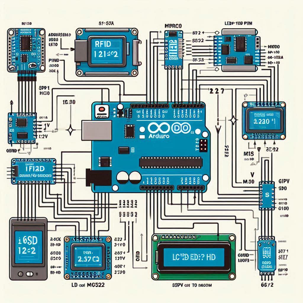
3D Block Diagram

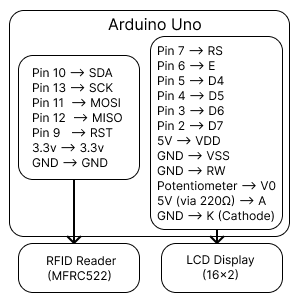
Simple Block Diagram

Step 4
Setting Up the Hardware
In this section, we’ll go step-by-step through the process of setting up the hardware components for the RFID-based attendance system. We’ll cover how to connect the RFID reader (MFRC522) and the LCD display to the Arduino Uno.
Connecting the RFID Reader (MFRC522)
The RFID reader (MFRC522) is the component that reads the RFID tags and sends the unique identifier (UID) to the Arduino. Here’s how to connect it:
SDA (Serial Data) to Digital Pin 10 on Arduino
SDA is used for communication between the RFID reader and the Arduino. It’s connected to Digital Pin 10.
SCK (Serial Clock) to Digital Pin 13 on Arduino
SCK sends the clock signal to synchronize data transmission between the RFID reader and the Arduino. It’s connected to Digital Pin 13.
MOSI (Master Out Slave In) to Digital Pin 11 on Arduino
MOSI is the data line for sending information from the Arduino (master) to the RFID reader (slave). It’s connected to Digital Pin 11.
MISO (Master In Slave Out) to Digital Pin 12 on Arduino
MISO is the data line for sending information from the RFID reader back to the Arduino. It’s connected to Digital Pin 12.
IRQ (Interrupt Request) – Not Connected
IRQ is not used in this project, so you can leave it unconnected. connection ( IRQ → Not Connected )
GND (Ground) to GND on Arduino
GND is the common ground connection. It’s connected to the GND pin on the Arduino to complete the circuit.
RST (Reset) to Digital Pin 9 on Arduino
RST is used to reset the RFID reader. It’s connected to Digital Pin 9. connection ( RST → Digital Pin 9 )
3.3V to 3.3V on Arduino
The RFID reader operates at 3.3V. Connect this pin to the 3.3V pin on the Arduino. connection ( 3.3V → 3.3V )
Connecting the LCD Display
The 16×2 LCD display will show the status messages, such as whether access is granted or denied. Here’s how to connect it:
VSS to GND
VSS is the ground pin for the LCD. Connect it to the GND pin on the Arduino. connection ( VSS → GND )
VDD to 5V
VDD provides the power supply to the LCD. Connect it to the 5V pin on the Arduino. connection ( VDD → 5V )
V0 to the Middle Pin of the Potentiometer
V0 controls the contrast of the LCD. Connect this pin to the middle pin of the potentiometer.
The other two pins of the potentiometer should be connected to 5V and GND, allowing you to adjust the display contrast.
RS (Register Select) to Digital Pin 7 on Arduino
RS selects whether the data being sent is command data or display data. Connect it to Digital Pin 7.
RW (Read/Write) to GND
RW selects the mode of the LCD, either reading or writing. Since we’ll only be writing to the display, connect RW to GND.
E (Enable) to Digital Pin 6 on Arduino
E enables the writing to the display. Connect it to Digital Pin 6. connection ( Enable → Digital Pin 6 ).
D4 to Digital Pin 5 on Arduino
D4 is a data pin used to send data to the LCD. Connect it to Digital Pin 5. Connection ( D4 → Digital Pin 5 )
D5 to Digital Pin 4 on Arduino
D5 is another data pin used to send data to the LCD. Connect it to Digital Pin 4. Connection ( D5 → Digital Pin 4 )
D6 to Digital Pin 3 on Arduino
D6 is another data pin used to send data to the LCD. Connect it to Digital Pin 3. Connection ( D6 → Digital Pin 3 )
D7 to Digital Pin 2 on Arduino
D7 is another data pin used to send data to the LCD. Connect it to Digital Pin 2. Connection ( D7 → Digital Pin 2 )
A (Anode) to 5V (through a 220-ohm resistor)
A is the anode for the backlight of the LCD. Connect it to 5V, but place a 220-ohm resistor in between to limit the current and protect the backlight.
K (Cathode) to GND
K is the cathode for the backlight of the LCD. Connect it directly to GND. Connection ( K → GND )
Step 5
Arduino Code
Programming the Arduino
Before diving into the Arduino code, ensure you have the necessary libraries installed. You’ll need the MFRC522 library for the RFID reader and the Liquid-Crystal library for the LCD display. You can install these libraries via the Arduino Library Manager.
Here’s the full Arduino code for the RFID-based attendance system:
Integrating the RFID Reader
The RFID reader (MFRC522) communicates with the Arduino using the SPI protocol. In the code above, we initialize the RFID reader in the setup() function and continuously check for new RFID tags in the loop() function.
When a new RFID tag is detected, its UID (Unique Identifier) is read and compared with a list of predefined UIDs. If the UID matches a known UID, access is granted, and a message is displayed on the LCD. Additionally, a buzzer can provide audible feedback.
Step 6
EEPROM Code
Storing and Retrieving Attendance Data
To make the attendance system functional, we need to store and retrieve attendance data. There are several ways to achieve this, including:
- Storing data on an SD card
- Using an online database
- Saving data to an EEPROM
For simplicity, we’ll use the Arduino’s internal EEPROM to store attendance data.
Storing Data in EEPROM
In this code, the storeAttendance function writes the UID of the RFID tag to the EEPROM, and the retrieveAttendance function reads the stored UIDs from the EEPROM and prints them to the serial monitor.
Building the User Interface
A user-friendly interface is crucial for any attendance system. The LCD display serves as the primary interface, providing real-time feedback on the status of each scan. You can enhance the interface by adding more functionality, such as:
- Displaying the time and date of each scan
- Showing the total number of attendees
- Providing options for administrators to view or clear the attendance log
Adding Date and Time
To display the current date and time, you can use an RTC (Real-Time Clock) module like the DS3231. Here’s how to integrate the RTC module into the system:
Connect the RTC Module:
(SCL to A5), (SDA to A4), (VCC to 5V), (GND to GND)
Include the RTC Library:
Initialize the RTC in the ‘setup‘ function:
Display Date and Time in the ‘loop‘ function:
Step 7
Enhancing the System
Once your basic RFID-based attendance system is up and running, you can add several enhancements to improve its functionality and usability:
Adding Wi-Fi Connectivity
By incorporating a Wi-Fi module like the ESP8266, you can connect your system to the internet and store attendance data in an online database. This allows for remote access and real-time monitoring.
Using a Touchscreen Interface
A touchscreen display can replace the LCD and provide a more interactive and user-friendly interface. You can add features like viewing attendance logs, setting alarms, and customizing messages.
Integrating with Existing Systems
To make the attendance system more versatile, you can integrate it with existing systems such as school management software or office HR systems. This can automate processes and reduce manual work.
Testing and Debugging
Testing and debugging are essential steps in building a reliable attendance system. Here are some tips to help you through the process:
- Check Connections: Ensure all connections are secure and correctly wired.
- Serial Monitor: Use the serial monitor to debug and print important information, such as UID readings and attendance logs.
- LCD Display: Verify that the LCD display is showing the correct information.
- EEPROM: Ensure data is being stored and retrieved correctly from the EEPROM.
Related Topics
Conclusion
Building an RFID-based attendance system with Arduino is a rewarding project that combines hardware and software skills. By following the steps outlined in this blog, you can create a system that is both efficient and user-friendly. Whether you’re implementing this in a school, office, or any other organization, the benefits of an automated attendance system are clear.
Feel free to modify and enhance the system to suit your specific needs. With the power of Arduino and RFID technology, the possibilities are endless. Happy building!


Leave a Reply