Real-Time Air Quality Monitoring Device
Building a Real-time Air Quality Monitoring Device
Build your own real-time air quality monitor with this detailed guide! Learn about essential components, assembly, and programming for accurate environmental data.
With growing concerns about air pollution and its impact on human health, real-time air quality monitoring has become increasingly important. Building your own air quality monitoring device not only provides you with valuable data but also empowers you to contribute to broader environmental efforts. In this guide, we will walk you through the process of building a real-time air quality monitoring device, explaining the concepts in detail and ensuring that the information is easy to understand.
Step 1
Understanding Air Quality
Before diving into the construction of the device, it is crucial to understand the key concepts related to air quality. Air quality is typically measured based on the concentration of various pollutants in the air, including:
- Particulate Matter (PM): Tiny particles suspended in the air, such as PM2.5 and PM10, which can penetrate deep into the lungs and cause health issues.
- Carbon Monoxide (CO): A colorless, odorless gas produced by burning fossil fuels, which can be harmful when inhaled in large amounts.
- Nitrogen Dioxide (NO2): A gas produced by vehicle emissions and industrial processes, which can irritate the respiratory system.
- Ozone (O3): A gas that forms in the atmosphere and can cause respiratory problems.
- Volatile Organic Compounds (VOCs): Organic chemicals that can evaporate into the air and cause various health effects.
Step 2
Components of the Air Quality Monitoring Device
To build a real-time air quality monitoring device, you will need a variety of components that work together to collect, process, and transmit air quality data. Here is a detailed breakdown of each component required for the device:
Microcontroller
The microcontroller acts as the brain of the device, responsible for processing data received from the sensors and managing communication with external servers. Popular choices for microcontrollers include:
- Arduino UNO: A popular choice for beginners, featuring an ATmega328P microcontroller, 14 digital I/O pins, 6 analog inputs, and USB connectivity.
- Raspberry Pi 4 Model B: Equipped with a quad-core Cortex-A72 CPU, 2GB/4GB/8GB RAM options, and extensive connectivity options including Wi-Fi and Bluetooth.
- ESP32 Dev Kit: An affordable and powerful microcontroller with dual-core processors, integrated Wi-Fi and Bluetooth, and multiple GPIO pins.
Air Quality Sensors
These sensors detect various pollutants in the air. Each sensor is designed to measure specific types of pollutants:
SDS011 PM2.5/PM10 Sensor:
- Measures fine particulate matter using laser scattering technology.
- Provides real-time data on PM2.5 and PM10 concentrations.
- Easy to interface with microcontrollers via serial communication.
MQ-7 CO Sensor:
- Electrochemical sensor designed to detect carbon monoxide.
- Provides analog voltage output proportional to CO concentration.
MQ-135 NO2 Sensor:
- Measures nitrogen dioxide levels along with other gases like ammonia, benzene, and alcohol.
- Analog voltage output that varies with gas concentration.
MQ-131 O3 Sensor:
- Sensitive to ozone, providing accurate measurements.
- Analog output for easy interfacing with microcontrollers.
MQ-2 VOC Sensor:
- Detects a wide range of volatile organic compounds.
- Provides analog output indicating the concentration of VOCs.
Wi-Fi Module
The Wi-Fi module allows the device to connect to the internet and send data to a remote server or cloud platform for storage and analysis. This is especially important for real-time monitoring and remote access to air quality data. If you are using a microcontroller with built-in Wi-Fi capabilities, such as the ESP8266 or ESP32, you will not need a separate Wi-Fi module.
ESP8266 Wi-Fi Module:
- Standalone Wi-Fi module with a full TCP/IP stack.
- Compatible with various microcontrollers for adding Wi-Fi capabilities.
- Affordable and widely used in IoT projects.
ESP32 (Built-in Wi-Fi):
- Dual-core microcontroller with integrated Wi-Fi and Bluetooth.
- Eliminates the need for a separate Wi-Fi module.
Power Supply
A reliable power source is essential to keep the microcontroller and sensors running. Depending on your setup, you can use:
Lithium-ion Battery Pack:
- Rechargeable batteries offering portability.
- Provides stable power output and long runtime.
USB Power Adapter:
- Standard 5V USB power adapter for continuous power supply.
- Suitable for indoor use with access to power outlets.
Solar Panel Kit:
- Solar panels with a charge controller and battery pack.
- Sustainable power solution for outdoor monitoring.
Casing
A protective enclosure is necessary to shield the device from environmental factors such as dust, moisture, and physical damage. The casing should allow adequate airflow for the sensors while protecting the electronic components. Options for the casing include:
3D Printed Enclosure:
- Customizable designs to fit all components perfectly.
- Lightweight and durable material.
Plastic Project Box:
- Ready-made enclosures available in various sizes.
- Easy to modify with drill holes for sensors and connectors.
DIY Enclosure:
- Assembled from acrylic sheets or other materials.
- Cost-effective and customizable.
Additional Components
These components are necessary for connecting and securing the various parts of the device:
Breadboard:
- Solderless platform for building and testing circuits.
- Facilitates easy modifications and connections.
Jumper Wires:
- Male-to-male, male-to-female, and female-to-female wires for versatile connections.
- Essential for connecting sensors and microcontroller pins.
Resistors and Capacitors:
- Various values to ensure proper circuit functionality.
- Used for voltage regulation, filtering, and signal conditioning.
Connectors:
- Header pins, screw terminals, and connectors for secure and reliable connections.
- Simplifies wiring and component integration.
By carefully selecting and integrating these components, you can create a robust and reliable real-time air quality monitoring device. This device will enable you to measure and analyze air quality data, providing valuable insights into the environment and helping to take informed actions to protect health and well-being.
Step 3
Circuit Design
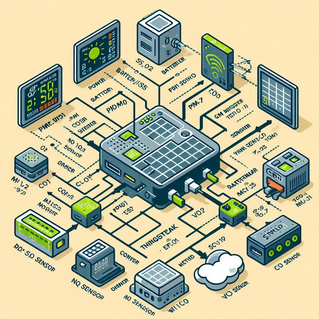
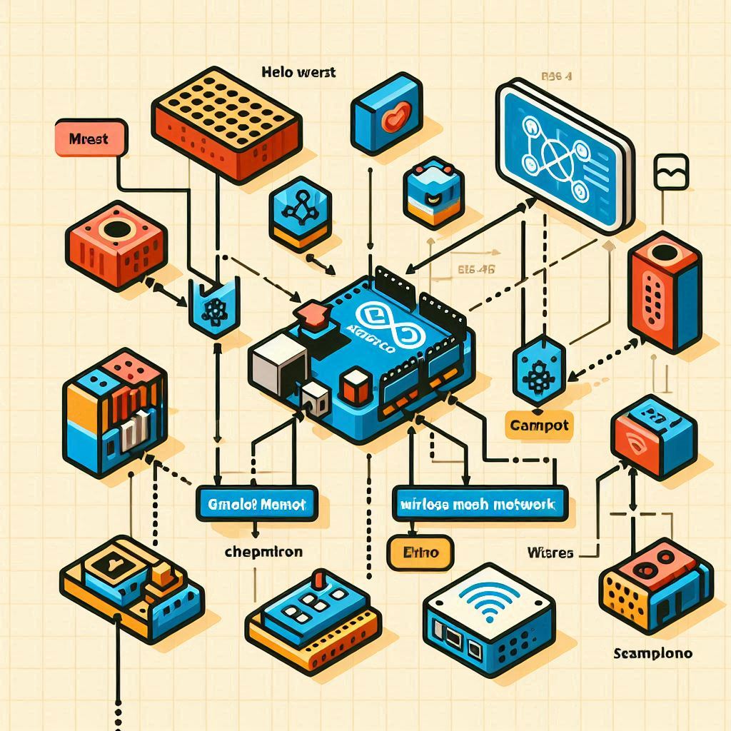
3D Block Diagram
Simple Block Diagram
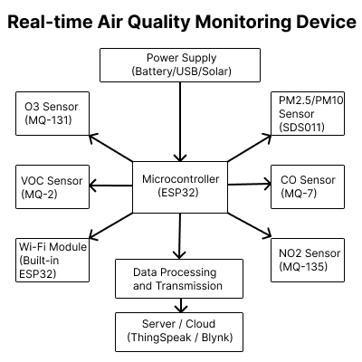
Explanation:
- Power Supply: Provides the necessary power to the microcontroller and sensors. It can be a battery, USB power, or solar panel.
- Microcontroller (ESP32): The central unit that reads data from all sensors, processes it, and sends it to the cloud server via the built-in Wi-Fi module.
-
Air Quality Sensors:
- PM2.5/PM10 Sensor (SDS011): Measures particulate matter levels and communicates with the ESP32 via UART (TX to RX and RX to TX).
- CO Sensor (MQ-7): Measures carbon monoxide levels and connects to an analog input pin on the ESP32.
- NO2 Sensor (MQ-135): Measures nitrogen dioxide levels and connects to another analog input pin.
- O3 Sensor (MQ-131): Measures ozone levels and connects similarly to the ESP32.
- VOC Sensor (MQ-2): Measures volatile organic compounds and connects to an analog input pin.
- Wi-Fi Module: Integrated in ESP32, used to connect to the internet and send data to the cloud server.
- Server/Cloud (ThingSpeak/Blynk): Receives data from the ESP32, stores it, and provides tools for visualization and analysis.
This block diagram as a for assembling the hardware components and understanding the flow of data from sensors to the cloud server. By following this, you can ensure that all connections are correctly made and that the device functions as intended.
Step 4
Step-by-Step Guide to Building the Device
Building a real-time air quality monitoring device involves several steps, each requiring careful attention to detail. Here’s a comprehensive guide:
Step 1: Setting Up the Microcontroller
Choosing the Microcontroller:
- ESP32 is a recommended choice due to its built-in Wi-Fi capabilities, affordability, and extensive community support.
- Alternatively, Arduino or Raspberry Pi can be used based on project requirements and familiarity.
Installing the IDE:
- Download and install the Arduino IDE from the official website.
- Configure the IDE to recognize the ESP32 by adding the appropriate board manager URL in the preferences.
Configuring the IDE:
- Open the Arduino IDE, go to
File > Preferences, and addhttps://dl.espressif.com/dl/package_esp32_index.jsonin theAdditional Boards Manager URLsfield. - Go to
Tools > Board > Boards Manager, search forESP32, and install the package.
Step 2: Connecting the Sensors
PM2.5/PM10 Sensor (e.g., SDS011):
- Connect the sensor’s TX pin to the ESP32’s RX pin.
- Connect the sensor’s RX pin to the ESP32’s TX pin.
- Connect the sensor’s VCC to the 5V pin of the ESP32 and GND to GND.
CO Sensor (e.g., MQ-7):
- Connect the sensor’s VCC to the 5V pin of the ESP32.
- Connect the sensor’s GND to the GND pin.
- Connect the sensor’s analog output (AO) to an analog input pin on the ESP32 (e.g., A0).
NO2 Sensor (e.g., MQ-135):
- Connect the sensor’s VCC to the 5V pin of the ESP32.
- Connect the sensor’s GND to the GND pin.
- Connect the sensor’s analog output (AO) to an analog input pin on the ESP32 (e.g., A1).
O3 Sensor (e.g., MQ-131):
- Connect the sensor’s VCC to the 5V pin of the ESP32.
- Connect the sensor’s GND to the GND pin.
- Connect the sensor’s analog output (AO) to an analog input pin on the ESP32 (e.g., A2).
VOC Sensor (e.g., MQ-2):
- Connect the sensor’s VCC to the 5V pin of the ESP32.
- Connect the sensor’s GND to the GND pin.
- Connect the sensor’s analog output (AO) to an analog input pin on the ESP32 (e.g., A3).
Step 3: Programming the Microcontroller
Library Installation:
- Install necessary libraries for the sensors, such as the
SdsDustSensorlibrary for the SDS011. - Use the Arduino IDE to manage and include these libraries in your project.
Writing the Code:
- Develop code to read data from each sensor and print it to the serial monitor.
- Configure the ESP32 to connect to a Wi-Fi network for data transmission.
Uploading the Code:
- Connect the ESP32 to your computer using a USB cable.
- Use the Arduino IDE to compile and upload the code to the microcontroller.
Step 4: Sending Data to a Server
Setting Up a Server:
- Use online services like ThingSpeak, Blynk, or set up your own server to collect and visualize data.
- Create an account and obtain the necessary API keys for data transmission.
Modifying the Code:
- Update your code to send sensor data to the server using HTTP requests or other relevant protocols.
- Ensure the data is formatted correctly to be accepted by the server.
Step 5: Building the Enclosure
Designing the Enclosure:
- Use CAD software like Tinkercad or Fusion 360 to design a custom enclosure.
- Ensure the design includes ventilation for the sensors and openings for power and data connections.
3D Printing the Enclosure:
- If you have access to a 3D printer, print the designed enclosure.
- Alternatively, use a pre-made project box and modify it as needed.
Assembling the Components:
- Secure the microcontroller, sensors, and power supply inside the enclosure.
- Ensure all components are properly connected and the enclosure is sealed to protect against environmental factors.
Additional Considerations
-
Calibration:
- Regularly calibrate your sensors according to the manufacturer’s instructions to ensure accurate readings.
-
Data Interpretation:
- Learn to interpret the data provided by your device to understand the implications for air quality and health.
-
Community Sharing:
- Consider sharing your data with local communities or online platforms to contribute to larger environmental monitoring efforts.
-
Expanding Functionality:
- Enhance your device by adding more sensors, integrating with home automation systems, or using machine learning for data analysis and predictions.
By following these steps, you can build a robust and reliable real-time air quality monitoring device. This will help you gain valuable insights into your environment and take informed actions to protect health and well-being.
Related Project ideas
Step 5
Other
Conclusion
Building a real-time air quality monitoring device involves understanding air quality parameters, selecting appropriate components, connecting sensors to a microcontroller, programming the device, and setting up data transmission to a server. By following this comprehensive guide, you can create a device that provides valuable insights into the air quality in your environment, helping you take informed actions to protect your health and the environment.
Additional Tips and Considerations
Calibration: Regularly calibrate your sensors to ensure accurate readings. Some sensors may require specific calibration procedures as outlined in their datasheets.
Data Interpretation: Learn how to interpret the data from your device. Understand the health impacts of various pollutant levels and take appropriate measures.
Community Sharing: Consider sharing your data with local communities or online platforms to contribute to broader environmental monitoring efforts.
Expanding Functionality: Enhance your device by adding more sensors, integrating it with home automation systems, or using machine learning algorithms for predictive analysis.


Leave a Reply